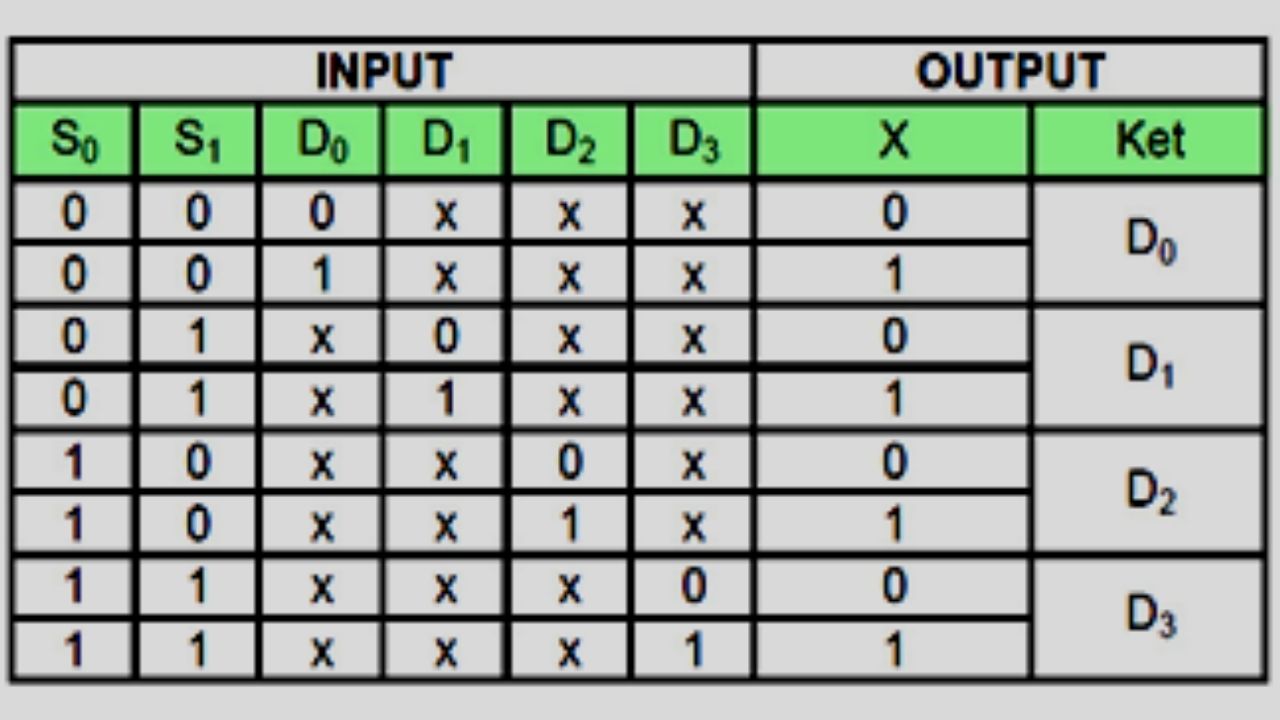
05 cara kerja dan tabel kebenaran Multiplexer dan Demultiplexer YouTube

2x1 Mux Schematic
Circuit Description. Circuit Graph. The circuit switches two two-bit input data A and B for transmission to the output. When the data select (S) input is 0, the odd-numbered AND gates are masked keeping their output low regardless of the logic state of B. The even-numbered AND gates, on the other hand, follow the logic state of A.

4x1 2bit Multiplexer Circuit Diagram
Multiplexer yang juga sering disingkat menjadi MUX atau MPX ini pada dasarnya berupa rangkaian digital yang dibuat dari gerbang logika berkecepatan tinggi yang digunakan untuk beralih data digital atau biner atau dapat berupa tipe analog yang menggunakan komponen transistor, MOSFET atau relay untuk mengalihkan salah satu input ke output [3].
Multiplexer in Digital Electronics, Block Diagram, Designing, and Logic Diagram
Input A dari 2-1 baris rangkaian multiplexer sederhana ini dibangun dari gerbang NAND standar bertindak untuk mengontrol input (I 0 atau I 1) akan dilewatkan ke output di Q . Dari tabel kebenaran di atas, kita dapat melihat bahwa ketika data memilih input, A adalah RENDAH pada logika 0, input I 1 meneruskan datanya melalui rangkaian multiplexer gerbang NAND ke output, sedangkan input I 0 diblokir.

2bit 4x1 Mux Circuit Diagram
setiap sinyal. Interleaving bisa dilakukan pada level bit atau pada blok-blok byte atau dalam jumlah besar. Sebagai contoh, multiplexer pada gambar 8.2 memiliki enam input di mana setiap input katakanlah sebesar 9,6 kbps. Jalur tunggal dengan kapasitas sedikitnya 757,6 kbps (plus kapasitas overhead) dapat memuat keenam sumber itu.

8 Bit logical right implementation using 2X1 MUX. Download Scientific Diagram
How to design a 3-bit multiplier? Consider two general 3-bit binary numbers A2A1A0 and B2B1B0. Multiplying the two numbers with each other using standard binary arithmetic rules, we get the following equation. Adding A2B0 and A1B1 will give rise to one carry, adding the sum obtained from that, and the carry obtained from adding A1B0 and A0B1 to.

PROTEUS TUTORIAL Cara membuat rangkaian Multiplexer 4x1 dengan proteus YouTube
Multiplexer adalah?☑️ Penjelasan apa itu Multiplexer☑️ Jenis, Fungsi, Cara Kerja , Tabel Kebenaran dan Contoh Rangkaian Lengkap☑️ Multiplexer merupakan suatu komponen elektronika atau alat tertentu yang dipakai untuk memilih 2 atau lebih masukan agar bisa meneruskannya menuju bagian keluaran. Biasanya, alat yang begitu canggih ini sudah biasa ditemukan di dalam kehidupan sehari.

Multiplexer Pengertian, Fungsi, Jenis, Cara Kerja
A multiplexer, abbreviated mux, is a device that has multiple inputs and one output. The schematic symbol for multiplexers is. Using a 1-to-2 decoder as part of the circuit, we can express this circuit easily. Multiplexers can also be expanded with the same naming conventions as demultiplexers. A 4-to-1 multiplexer circuit is.

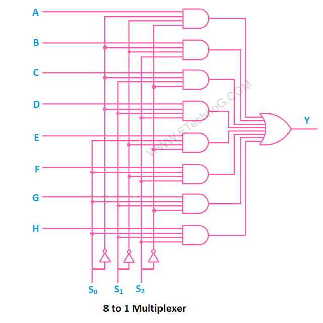
Rangkaian Multiplexer
The circuit switches two two-bit input data A and B for transmission to the output. When the data select (S) input is 0, the odd-numbered AND gates are masked keeping their output low regardless of the logic state of B. The even-numbered AND gates, on the other hand, follow the logic state of A. Therefore B is blocked while A is allowed to be.

Tabel Kebenaran Multiplexer
Multiplexers in Digital Logic. A multiplexer is a combinational circuit that has many data inputs and a single output, depending on control or select inputs. For N input lines, log2 (N) selection lines are required, or equivalently, for 2^n input lines, n selection lines are needed. Multiplexers are also known as "N-to-1 selectors.

05 cara kerja dan tabel kebenaran Multiplexer dan Demultiplexer YouTube
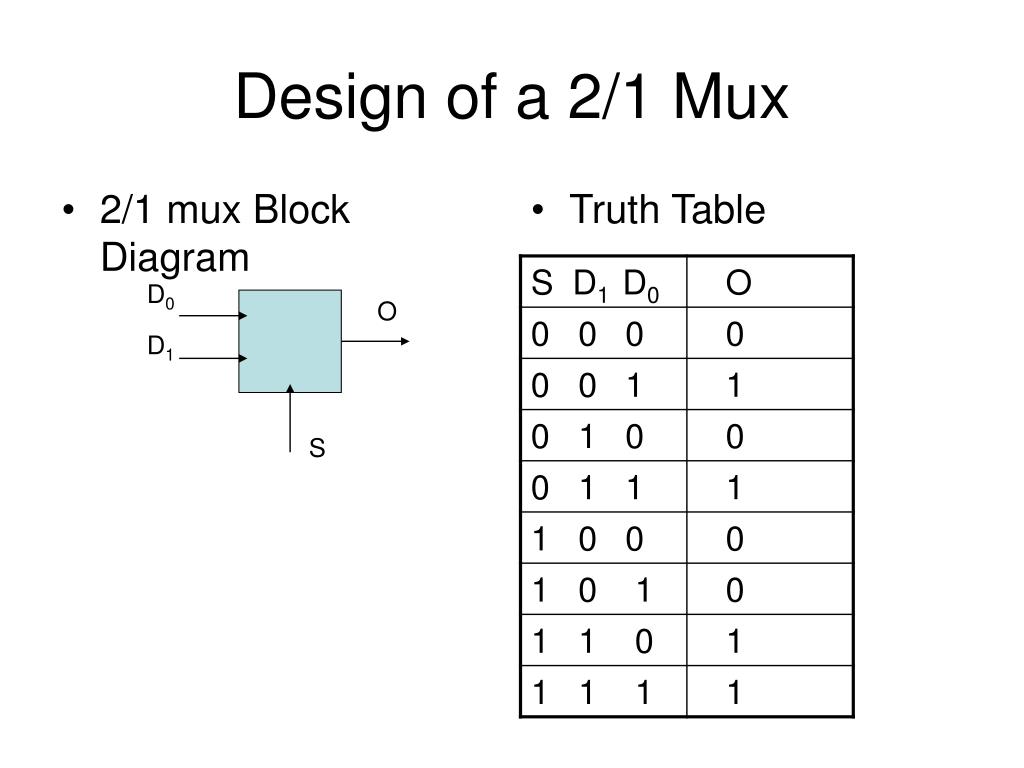
A 2-to-1 multiplexer is the digital multiplexer circuit that has two data inputs D 0 and D 1, one selects line S and one output Y. To implement a 2-to-1 multiplexer circuit we need 2 AND gates, an OR gate, and a NOT gate. The block diagram, logic symbol and switching circuit analogy of 2-to-1 multiplexer is shown in the figure below. A 2-to-1 Mux
TwoInput TwoBit Multiplexer Multisim Live
The webpages for the current completed WinLogiLab Android applications are: 1. BaseCon - Convert numbers between various numerical bases and between various binary codes. 2. Truth Table Minimiser - Minimise a Boolean Truth Table utilising Karnaugh Maps or the Quine-McCluskey algorithm. 3. TestKMap - Test the users ability to solve Karnaugh Map

4 Bit Multiplexer Circuit Diagram
Multiplexer 2 Input ini pada dasarnya dibangun dari gerbang NAND standar untuk mengendalikan input (I 0 atau I 1) mana yang akan diteruskan ke output pada Q. Dari tabel kebenaran di atas, dapat kita lihat bahwa pada saat memilih Input, apabila Terminal Pengendali A berada pada kondisi logika 0 (rendah), Input I 1 akan meneruskan datanya melalui rangkaian multiplexer gerbang NAND ke output.

Multiplexers YouTube
The most basic type of MUX, the one on which all larger MUXes are built, is a 1 bit MUX. As will be shown later in this section 8 bit 4-to-1 MUX is made up of eight 1 bit 4-to-1 MUX. So to understand multiplexers a 1 bit 4-to-1 multiplexer will be examined. A 1 bit 4-to-1 multiplexer has four 1-bit data inputs values (I 0-I 3) to choose

Multiplexer and Demultiplexer The ultimate guide
The figure below shows the block diagram of a 2-to-1 multiplexer which connects two 1-bit inputs to a common destination. The truth table of the 2-to-1 multiplexer is shown below. Depending on the value of the select input, the inputs i.e., D0, D1 are produced at outputs. The output is D0 when Select value is S = 0 and the output is D1 when.

2 1 Mux Circuit Diagram Wiring Diagram
When contrasted with the NMOS and bipolar transistors low force devoured by CMOS circuits. Standard cell based, semi-custom and full custom are the structure approaches used to configuration IC's. This paper depends on the area efficient 2:1 multiplexer utilizing microwind instrument. Figure 3 shows the schematic graph of 2:1 MUX.

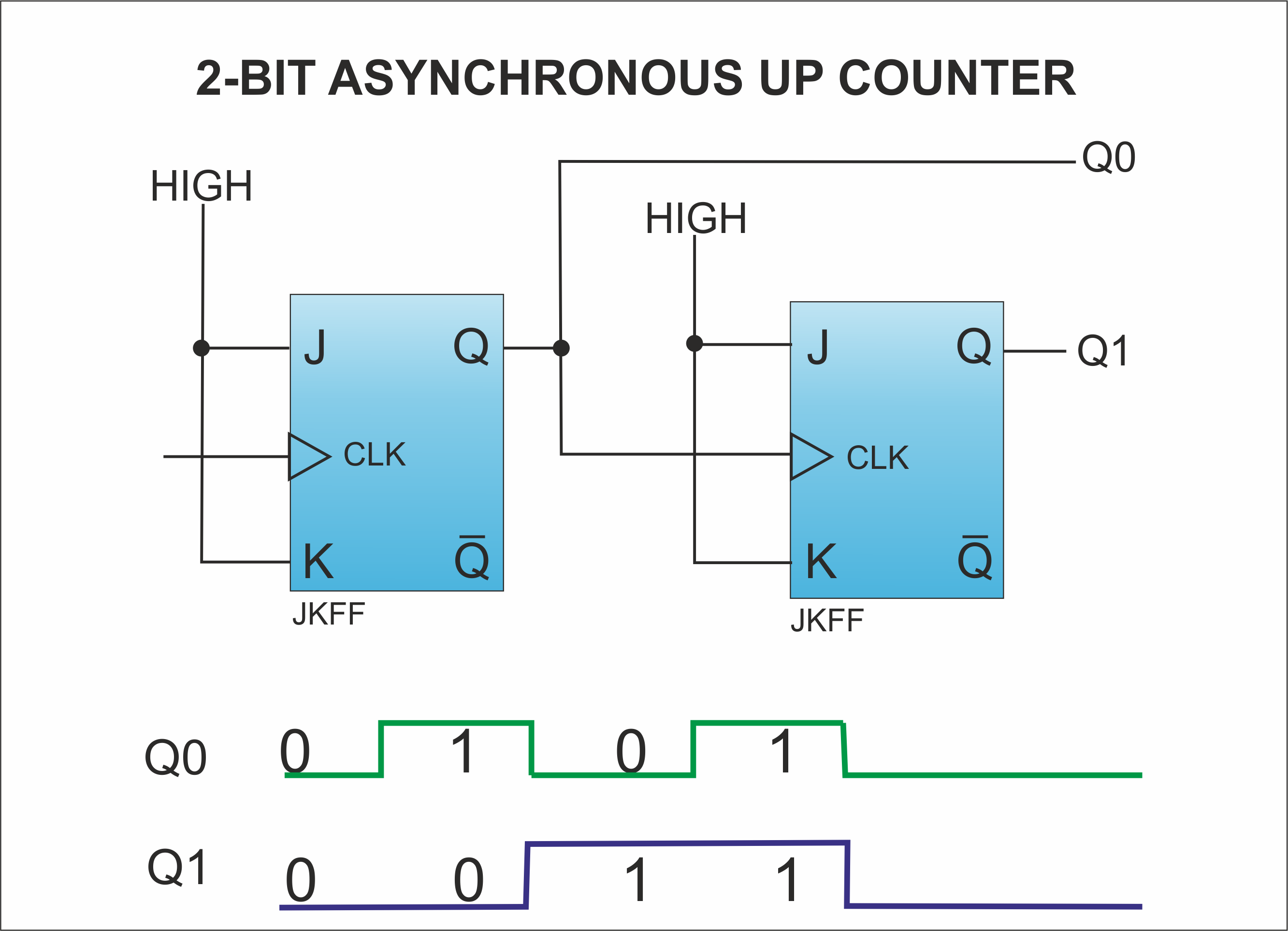
Multiplexer Decoder Flip Flop Dan Counter Lampu Siswa
Generally, the selection of each input line in a multiplexer is controlled by an additional set of inputs called control lines and according to the binary condition of these control inputs, either "HIGH" or "LOW" the appropriate data input is connected directly to the output. Normally, a multiplexer has an even number of 2 n data input lines and a number of "control" inputs that.