CircuitVerse 4 multiplexer using symbol
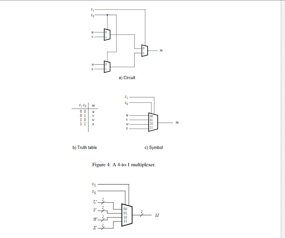
(Get Answer) A) Circuit 5150 M 00 U 01 V 10 W 11 X B) Truth Table C) Symbol... Transtutors
Using a 1-to-2 decoder as part of the circuit, we can express this circuit easily. Multiplexers can also be expanded with the same naming conventions as demultiplexers. A 4-to-1 multiplexer circuit is. That is the formal definition of a multiplexer. Informally, there is a lot of confusion. Both demultiplexers and multiplexers have similar names.

[DIAGRAM] Logic Diagram For 8 1 Multiplexer
Multiplexers. A multiplexer, abbreviated mux, is a device that has multiple inputs and one output. Using a 1-to-2 decoder as part of the circuit, we can express this circuit easily. Multiplexers can also be expanded with the same naming conventions as demultiplexers. A 4-to-1 multiplexer circuit is. That is the formal definition of a multiplexer.
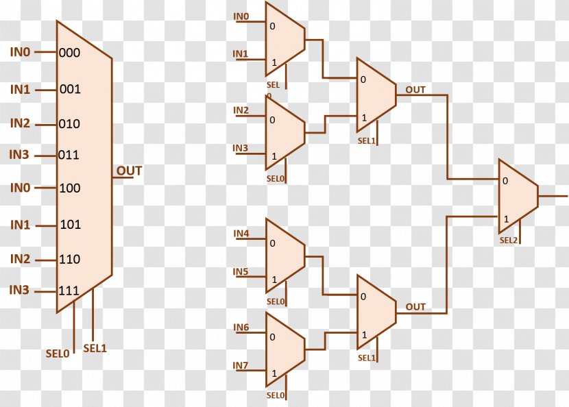
Multiplexer Circuit Diagram Schematic Truth Table Structure Lines Transparent PNG
Multiplexer- Multiplexing is the process of combining the different communication channels and transfer it over a single transmission medium is called multiplexing. Three types of multiplexing techniques are used. A multiplexer is a combinational logic circuit that receives 2 n input lines and convert it into a single output line.

pengen tau Rangkaian Multiplexer
It is the simplest two-line-to-one (2-to-1) Multiplexer. Figure 2: The Multiplexer symbol 2-to-1 Multiplexer. In the following figure, a 2-to-1 Multiplexer has been shown along with its truth table. Figure 3: The 2-to-1 Multiplexer along with Truth Table and Switch Analogy. The above 2-to-1 Multiplexer is constructed using only NAND gates.
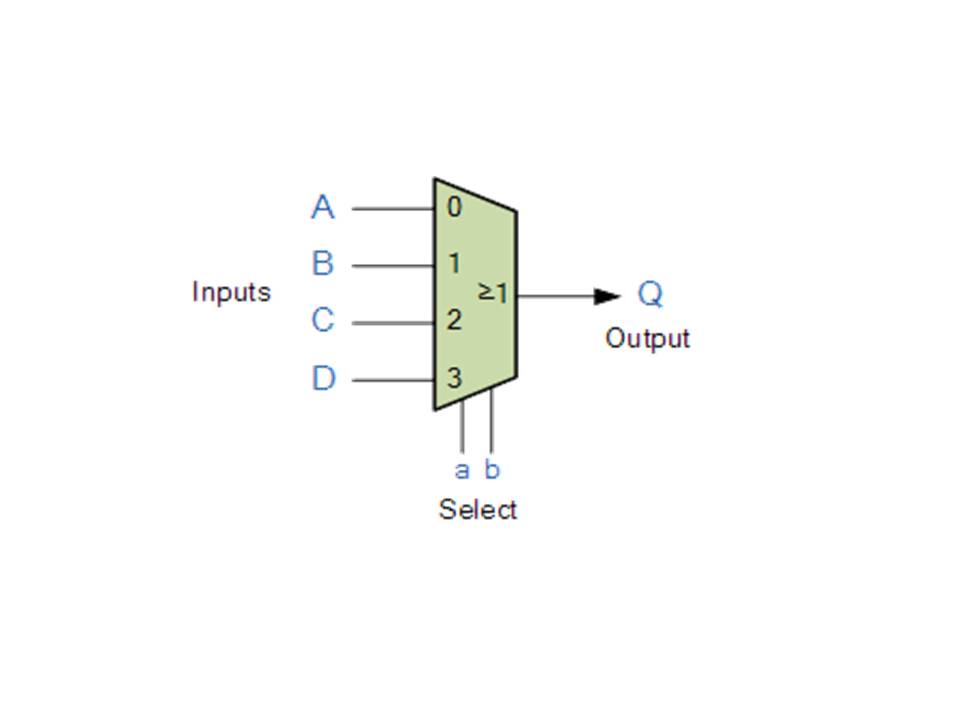
Multiplexer & Decoder ComPutEr???
• In figure 9.9, the outputs of two buffers are connected together, but only one of the two outputs is active at a time, the other is in Hi-Z • The circuit is logically equivalent to a 2:1 multiplexer • For the circuit from figure 9.10, if both buffers are enabled and if A=0 and C=1, then the value of the output F will be unknown.

4 To 1 Mux Schematic
The Multiplexer. Multiplexing is the generic term used to describe the operation of sending one or more analogue or digital signals over a common transmission line at different times or speeds and as such, the device we use to do just that is called the multiplexer. The multiplexer, shortened to "MUX" or "MPX", is a combinational logic.
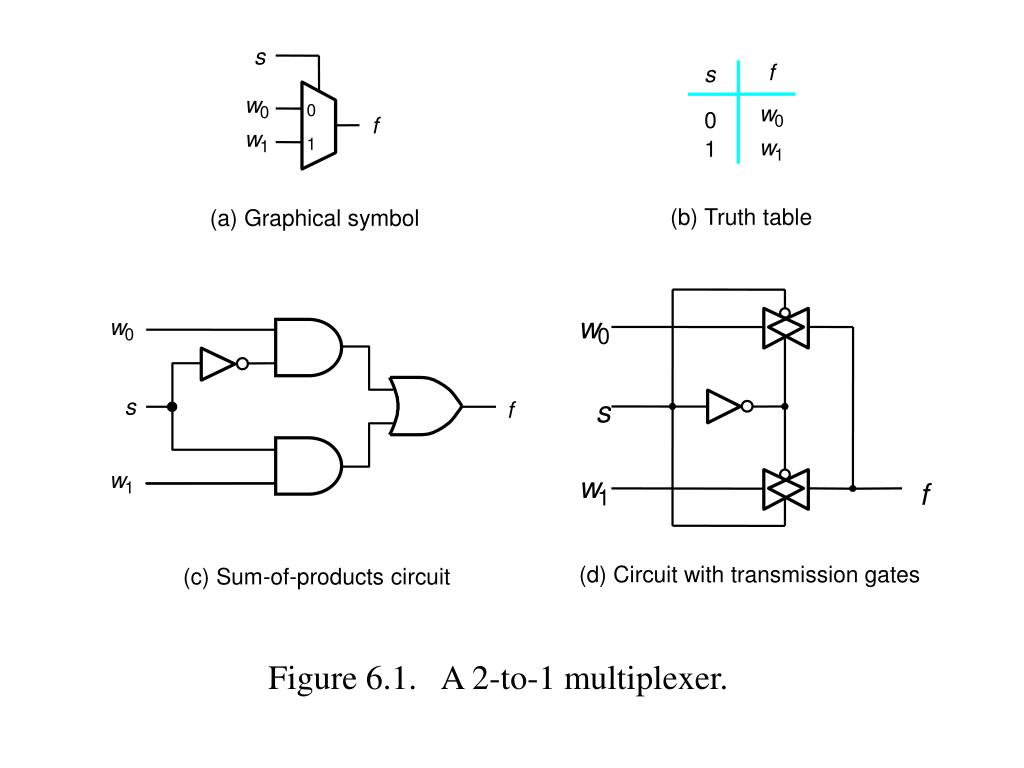
PPT Figure 6.1. A 2to1 multiplexer. PowerPoint Presentation, free download ID3296517
Multiplexers are used to separate the various bands. At the cross-over points in a continuous band of interest, the adjacent channels will have equal response in passing and rejecting the signal, ideally 3.01 dB. Thus there is a certain amount of dead zone in a wideband system. You might want to carefully pick where this occurs.
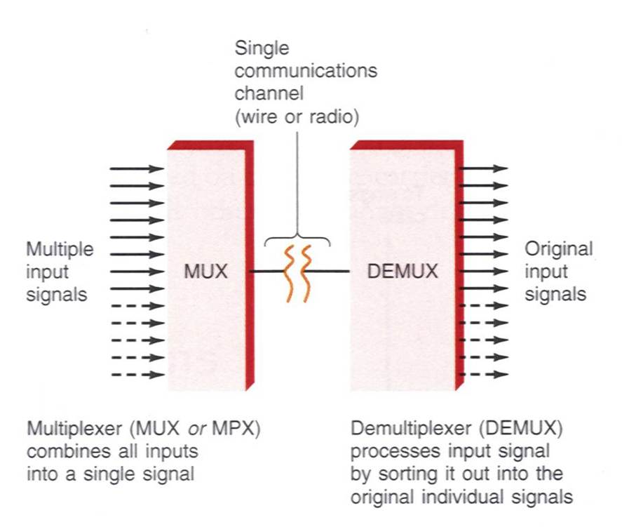
Mengenal Cara Kerja Multiplexer And Demultiplexer Dan Fungsinya
1 Answer. Sorted by: 8. This notation means a bus line with the width noted by the number written next to it. In your case it is 2-bit wide bus. It is used to make the drawing less convoluted by reducing lines drawn. Share.

4 To 1 Mux Schematic
A multiplexer selects one signal from multiple input signals and forwards it to a single output line. The following timing diagram shows how one signal is selected from two inputs. When the SELECT pin is Low (0), a signal is forwarded from the A pin to the Y pin. When the SELECT pin is High (1), a signal is forwarded from the B pin to the Y pin.

Multiplexer in Digital Electronics, Block Diagram, Designing, and Logic Diagram
Like a multiplexer, it can be equated to a controlled switch. In electronics, a multiplexer (or mux; spelled sometimes as multiplexor ), also known as a data selector, is a device that selects between several analog or digital input signals and forwards the selected input to a single output line. [1] The selection is directed by a separate set.

Rangkaian Multiplexer
A multiplexer, abbreviated mux, is a device that has multiple inputs and one output. The schematic symbol for multiplexers is. Using a 1-to-2 decoder as part of the circuit, we can express this circuit easily. Multiplexers can also be expanded with the same naming conventions as demultiplexers. A 4-to-1 multiplexer circuit is.

Multiplexer, Assignment Help, Combinational Circuits
8-1 multiplexer (3 baris) 8-1 multiplexer memiliki tiga input dan satu output, serta delapan pilihan sinyal input. Jenis multiplexer ini sering digunakan dalam rangkaian sistem kontrol dan pengaturan. 16-1 multiplexer (4 baris) 16-1 multiplexer memiliki empat input dan satu output, serta enam belas pilihan sinyal input.
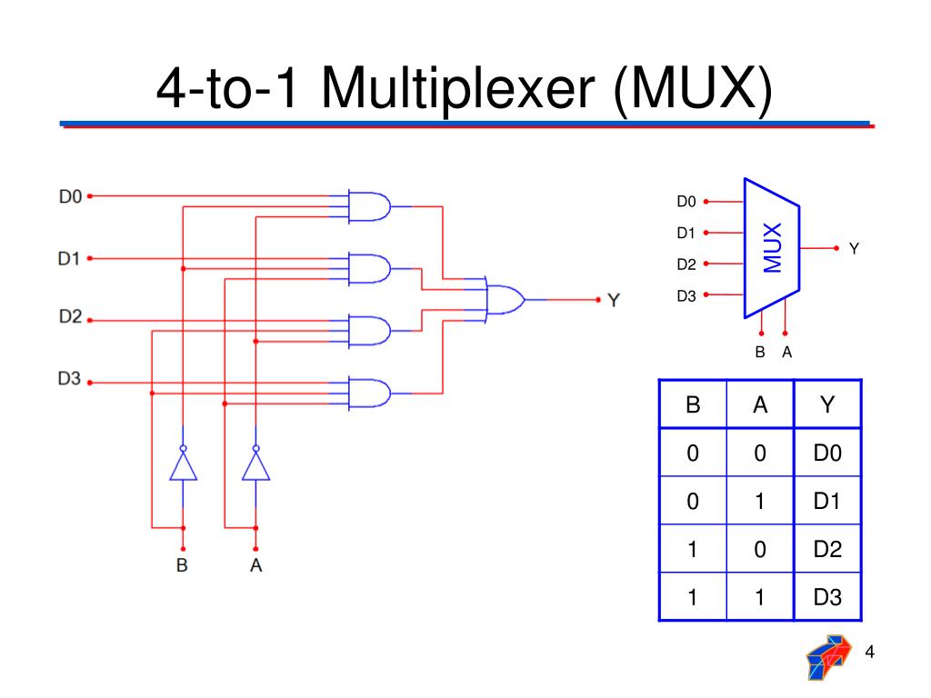
PPT Multiplexer / Demultiplexer PowerPoint Presentation, free download ID6108824
Multiplexers in Digital Logic. A multiplexer is a combinational circuit that has many data inputs and a single output, depending on control or select inputs. For N input lines, log2 (N) selection lines are required, or equivalently, for 2^n input lines, n selection lines are needed. Multiplexers are also known as "N-to-1 selectors.
Multiplexer in Digital Electronics, Block Diagram, Designing, and Logic Diagram
9.7: Multiplexers. A multiplexer, abbreviated mux, is a device that has multiple inputs and one output. The schematic symbol for multiplexers is. Using a 1-to-2 decoder as part of the circuit, we can express this circuit easily. Multiplexers can also be expanded with the same naming conventions as demultiplexers.
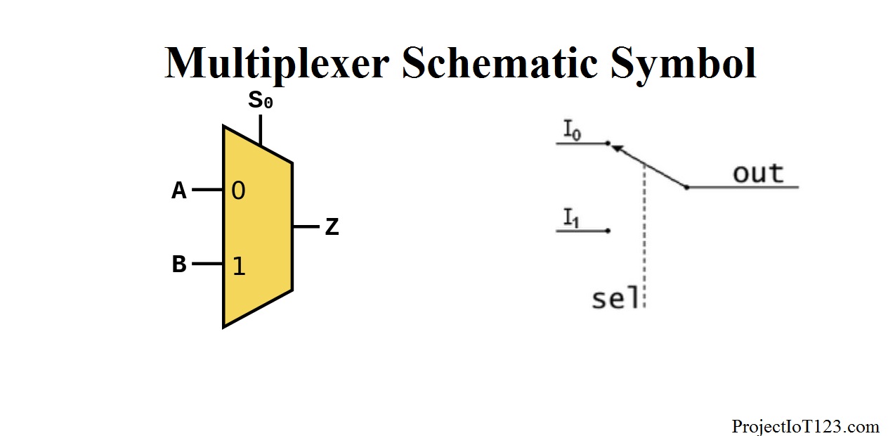
Introduction to Multiplexer projectiot123 Technology Information Website worldwide
Given the Boolean function, we can implement the 4×1 multiplexer using inverters in this circuit diagram. Circuit Diagram of 4×1 Multiplexer. Implementing a Multiplexer With an MC14052B IC. The MC14052B has two 4×1 multiplexers inside. It is an analog multiplexer so the input pins can use variable voltage as supply but it will have the same.
Circuit, diagram, electric, electronic, logic circuit symbol, multiplexer icon
A 2-to-1 multiplexer is the digital multiplexer circuit that has two data inputs D 0 and D 1, one selects line S and one output Y. To implement a 2-to-1 multiplexer circuit we need 2 AND gates, an OR gate, and a NOT gate. The block diagram, logic symbol and switching circuit analogy of 2-to-1 multiplexer is shown in the figure below. A 2-to-1 Mux